
LP-HV-256 high voltage LiFePO4 battery pack
A 256 V stack built from five of our standard 51.2 V modules, with the master-slave BMS and pre-charge arrangement that high-voltage systems require and low-voltage packs do not.
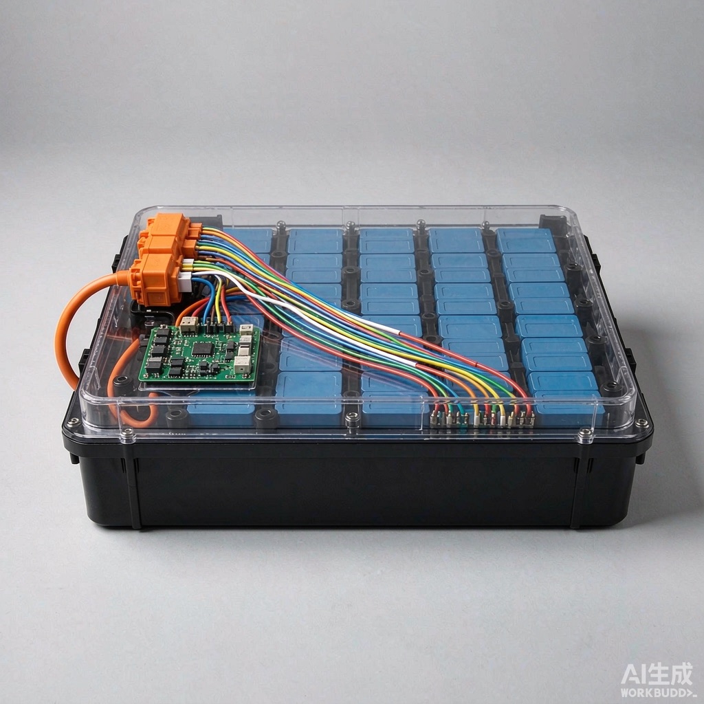 Product image
- Brand
- HighIdea
- Type
- High-voltage LiFePO4 stack, 5S module
- Typical applications
- Three-phase commercial inverters, industrial UPS, off-grid estates
- Models in range
- LP-HV-256 standard 25.6 kWh stack, LP-HV-256C cabinetised with integrated DC breaker, LP-HV-256X extended 6-module variant at 307 V
- Category
- Battery Packs
It is a system, not a component
Below about 100 V, a battery pack can be bought as a product. Above it, the pack becomes a system with electrical, thermal and safety design that has to be documented — for the certification body, and in most markets for the installer.
Four things are mandatory at this level and are all included in this platform:
- Master-slave BMS with one slave board per module measuring its own cells and temperatures, and a master that aggregates the stack, computes state of charge and health, and drives the contactors.
- Pre-charge circuit to protect the inverter's DC link and avoid welding a contactor on connection.
- Insulation monitoring to earth, with a contactor trip when isolation resistance degrades. Above low voltage, an earth fault is a hazard rather than a nuisance.
- Documented service disconnect — a lockable isolation point and protection coordinated with the inverter's own DC protection.
What we need to quote
High-voltage work is quoted from a requirement rather than a catalogue page. Send the inverter's DC voltage window, the continuous and peak power, the maximum charge and discharge current, the ambient conditions, the space available and the certification target. We return a single-line diagram, a module layout and a price for approval before any hardware is built.
On most projects this takes one exchange of documents. Where the customer already has an inverter and a grid-code obligation, we start from the inverter's DC specification and work backwards to the stack.
Key Features
- 256 V nominal from five 51.2 V modules in series
- 25.6 kWh rated energy
- {'Master-slave BMS': 'one slave per module, one master for the stack'}
- Pre-charge circuit and sequenced contactors to protect the inverter DC link
- Insulation monitoring to earth with contactor trip on degradation
- 100 A continuous discharge, 200 A peak
- Designed around our standard 51.2 V module, so spares stay available
Specifications
| Nominal voltage | 256 V (5 × 51.2 V) |
|---|---|
| Rated energy | 25.6 kWh |
| Usable energy | approximately 23 kWh at 90 % depth of discharge |
| Continuous discharge current | 100 A |
| Peak discharge current | 200 A for 10 s |
| Continuous charge current | 50 A recommended |
| BMS architecture | master-slave |
| Communication | CAN to inverter |
| Protection | over/under-voltage |
| Pre-charge | integrated |
| Enclosure | steel rack cabinet |
| Mass | approximately 340 kg including cabinet |
Specifications subject to the latest factory data. Final configuration is sized against the actual load, backup runtime and site power conditions — this table is for pre-selection only.
Applications
Three-phase commercial inverter
Matches the DC input window of most commercial three-phase hybrid inverters, with one CAN interface for the whole stack.
Industrial UPS DC link
Where the UPS is specified with a high-voltage DC bus and per-string battery management is required.
Off-grid estate
High voltage reduces DC cable cross-section over the long runs typical of estate-scale installations.
FAQ
Why go high voltage at all?
What is pre-charge and why does it need a separate circuit?
Can I add modules later?
Who signs off the installation?
Related Models
CI-100
A 100 kWh / 50 kW cabinet for behind-the-meter peak shaving and demand charge reduction — sized to connect to an existing low-voltage switchboard without civil works.
View detailsLP-HV-512
51.2 kWh at 512 V from ten standard modules — the platform for containerised storage and large commercial inverters where the DC bus is high voltage by design.
View detailsLP48-280
14.34 kWh in one enclosure with a 200 A BMS — the configuration for solar banks and industrial backup where fewer, larger units are easier to manage than a stack of small ones.
View details