
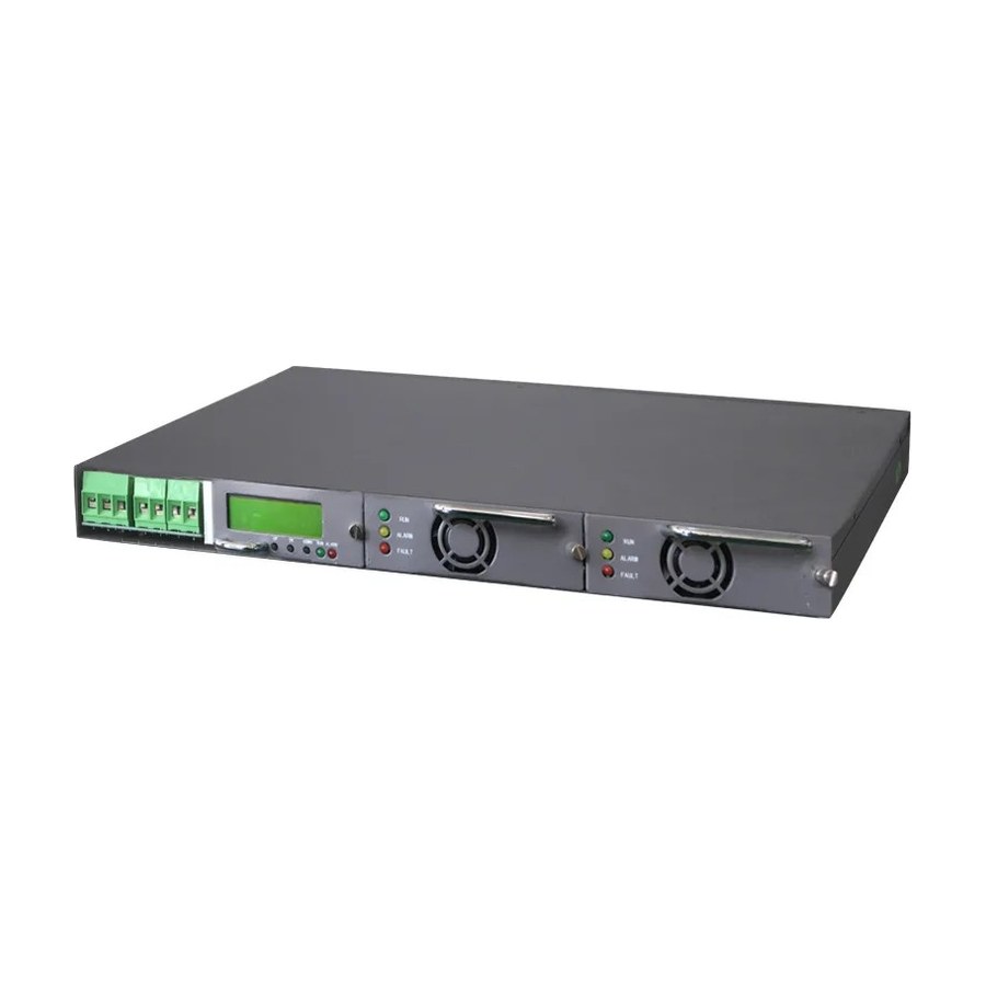
Selecting a 48V DC power system for a telecom room
Most telecom rooms still run on a -48V DC bus, and most power problems there trace back to decisions made at selection time, not to equipment failure. This guide walks through the rectifier sizing rules, the embedded-format trade-offs, and the rectifier-plus-inverter architecture that lets one battery bank feed both DC and AC loads.
The short answer
A telecom 48V DC power system is sized on four numbers: the measured load current, the battery charging current, the float-voltage window your battery chemistry needs, and the rack space you can actually spare. Configure rectifier modules in N+1, keep the bus voltage adjustable between roughly 53.5V and 56.4V so both lead-acid and LiFePO4 banks can be matched, and feed any AC loads from the same DC bus through a dedicated DC-AC inverter instead of installing a second UPS.
What the system actually consists of
Every -48V DC plant, from a carrier central office down to a single-rack edge site, is the same five blocks:
- AC input distribution — breakers, surge protection and a transfer point for a generator or second feeder.
- Rectifier modules — convert AC mains to regulated -48V DC; the block that should be redundant.
- DC distribution — branch breakers sized to each actual circuit.
- Battery bank — VRLA or LiFePO4, floating on the bus and carrying the full load instantly when AC fails.
- Supervision — bus voltage, per-module current, temperature and alarms over dry contacts, RS485/Modbus or IP.
The battery is the only block that works unseen for years at a time, which is exactly why the rectifier side that keeps it charged deserves the stricter sizing discipline.
Sizing the rectifier: current, redundancy and voltage window
Total rectifier capacity = load current + recharge current + margin. Measure the real load with a clamp meter — telecom equipment nameplates routinely overstate by 30–50% — add recharge current sized to recover the bank in 8–12 hours, and keep 20–30% headroom for growth. Module count follows N+1: if the arithmetic says two 60A modules, install three.
Lead-acid floats near 53.5–54.0V with equalization to about 56.4V; a 16S LiFePO4 pack wants a similar range with tighter cutoff behavior. A rectifier system whose output cannot be adjusted across this window locks you into one battery chemistry for the life of the plant. The RT4860 1U embedded rectifier system covers this window in a single rack unit; the larger RT 30-800A embedded power system scales the same approach for rooms measured in hundreds of amps.
| Parameter | Typical requirement | Why it matters |
|---|---|---|
| Float voltage range | 53.5–56.4V adjustable | Matches both lead-acid and LiFePO4 banks |
| Module configuration | N+1, hot-swappable | Single module failure must not drop the load |
| Full-load efficiency | ≥ 92% | Every lost point becomes heat the air conditioner pays for |
| Current sharing | ≤ ±5% between modules | Poor sharing ages the most-loaded module early |
| Monitoring | Dry contact + RS485 Modbus | Integration with the existing environment system |
| Recharge capability | 0.1–0.2C into the bank | Sets recovery speed after a long outage |
Why the embedded 1U/2U format wins in small rooms
Embedded rectifier systems package the functions of a floor-standing telecom power cabinet into standard 19-inch, 1U–2U chassis that share rack space with the transmission and switching equipment they feed. Three practical consequences:
- Shorter DC runs — bus bars give way to short cable drops, cutting voltage drop and emitted noise.
- Incremental capacity — start with one 30A module and add more as the rack fills.
Rooms that also carry 24V equipment — some microwave radios and legacy transport gear still do — are better served by a dedicated 1U 24V rectifier supply than by improvised regulation from the 48V bus. Where the mismatch runs the other direction (a 110V or 220V DC bus feeding 48V loads, or vice versa), a 2U DC-DC converter covering 24–220V bridges the voltage standards without an extra AC conversion stage and its efficiency loss.
Feeding AC loads from the same bus
Most telecom rooms carry a handful of AC-only devices: monitoring PCs, routers, work lights. The reflex is to add a conventional UPS with its own batteries — a second bank, charger and maintenance schedule for a few hundred watts of load.
The better architecture reuses the DC plant: unused rectifier headroom feeds a DC-AC inverter connected to the same -48V bus. During an AC outage the batteries carry the DC loads and the inverter together, and there is exactly one battery bank to maintain. A 48V to 220V inverter sized 1.5–2× above the steady AC load handles motor starts and inrush without dropping output.
Two sizing checks are mandatory before committing to this design. First, add the inverter's full-load DC draw to the rectifier capacity calculation — an inverter the bus plan never accounted for will silently discharge the battery on every outage. Second, confirm the inverter outputs a true sine wave; modified-sine output shortens the life of switching power supplies and can upset sensitive measurement equipment.
Mistakes that surface in year two
Two of them dominate the failure reports. First, sizing from nameplates: telecom equipment nameplates routinely overstate by 30–50%, so measure with a clamp meter, then add margin. Second, ignoring battery temperature compensation — float voltage that is right at 25°C overcharges a bank at 35°C and undercharges it at 5°C; either the rectifier supports compensation or the battery warranty quietly voids itself. Beyond those, check current sharing (modules that do not share within ±5% age at the rate of their worst member) and buy on lifecycle cost, not unit price — a slightly cheaper but less efficient module costs more in electricity within two years.
FAQ
Can an embedded 48V rectifier charge LiFePO4 batteries directly? Yes, provided the output adjustment range covers the pack's charge voltage. A 16S LiFePO4 bank charges in nearly the same window as a lead-acid float, so most modern telecom rectifiers handle both — confirm the pack's maximum charge voltage against the module's range, and disable any equalization stage that lead-acid presets would apply.
Can the rectifier system and the DC-AC inverter share one battery bank? Yes — sharing the bank is the entire economic argument for the architecture. The rectifier floats the bank and the inverter draws from the bus. Total module capacity must still cover DC loads, the inverter's AC load converted to DC current, and recharge current, with the usual 20–30% margin.How much rectifier redundancy is enough? N+1 for a single-room site: one more module than the load calculation requires, so any single module can fail without interruption. Sites with dual feeders or generator backup sometimes specify N+2; beyond that, redundancy stops buying reliability and starts buying shelf inventory.
What monitoring interface should be specified for a new installation? RS485 with Modbus RTU as the baseline, plus dry contacts for simple remote alarm. For unattended or distributed sites, add an IP-based monitoring card so bus voltage, module status and battery temperature reach a central platform. Standard Modbus costs nothing extra and avoids protocol mapping work during commissioning.